A lady with no technical background inherited a pile of assorted multimeters, and—rather unwisely—dared to ask in a Facebook group devoted to such things how much each might be worth. She did not receive many straight answers. Some people immediately latched onto one instrument or another and offered her a token amount; others promptly denounced those first bidders as shameless low-ballers, while of course never bothering to name an actual fair price themselves. I figured that while waiting for my food to arrive, I might as well help her sort out the pricing. A few resellers, I suspect, invoked my mother’s name later.
One of the instruments the lady was hoping to sell was a Novotest 2 TS 141 multimeter. I was tempted to buy it myself, but I simply have no space left for collecting hardware like this. So instead I did a bit of digging online and gathered everything I could about the device—expanding my virtual instrument collection, which takes up no room and gathers no dust. The images shown here are likewise harvested from the internet; they do not depict the specific unit she had for sale.
General description
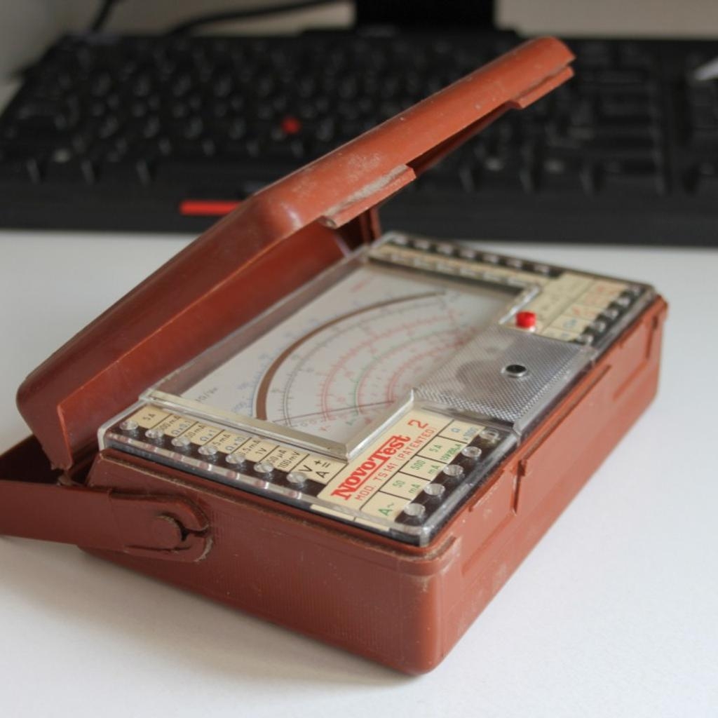
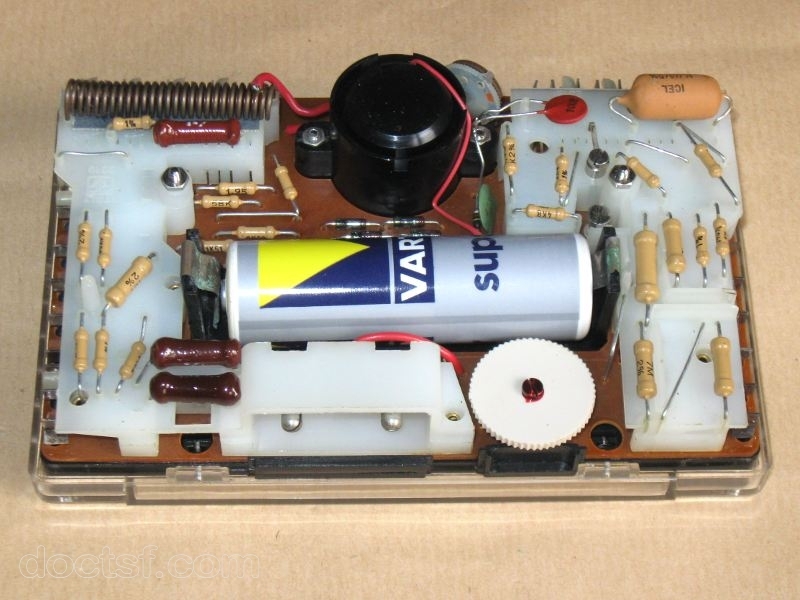
The little instrument is roughly my age; this model was manufactured by Cassinelli, S.a.s. & C. (CCM) in Milan in the late 1960s and early 1970s. It is fully analog—indeed, it contains no active electronics whatsoever. No transistors, no ICs, no trickery of any kind. The entire device is built around a mirror-scale Deprez-type moving-coil meter and a handful of resistors plus four diodes. It does have a battery: a 3-volt 2R10 dry cell used exclusively for resistance measurement—current and voltage ranges require no battery at all. The instrument measures 155 × 45 × 110 mm, and originally came in a neat little brown Bakelite case.
One curious feature of the instrument is that it has no range-selector switch at all; instead, you move the test leads from one socket to another to select the appropriate measurement range. Instruments like this did exist back in the day, but even in my youth the dominant solution was already the rotary range selector (the classic Yaxley switch). This plug-and-socket approach survived mainly in a few older German and Soviet meters, as well as in various home-built amateur designs.
Ernest E. Yaxley invented the Yaxley switch and patented it in the United States in 1925. The patent was assigned to the Yaxley Manufacturing Company of Chicago and to the Carter Radio Company. The product became widely known under the Mallory-Yaxley brand. In its time it was a significant innovation because it allowed switching among multiple circuits with a single rotary motion, offering a compact and versatile solution for contemporary radios, measuring instruments, and even aircraft instrument panels. The original construction used a multi-disc, sandwich-like assembly that enabled a large number of positions and the switching of many independent circuits. Today, the term “Yaxley” is often used generically to refer to any similar rotary switch. In modern handheld multimeters, it is standard practice to build virtually all functions around a single selector of this type.
Although rotary switches were already common on British and American instruments during the Second World War, some manufacturers continued to use the plug-and-socket method well into the 1970s. According to the old-timers, that approach had its advantages: it was harder to switch to the wrong range by accident. Its disadvantage, however, is reduced safety—during range changes, one might inadvertently touch the plug, which in unfavourable circumstances could deliver an electric shock.
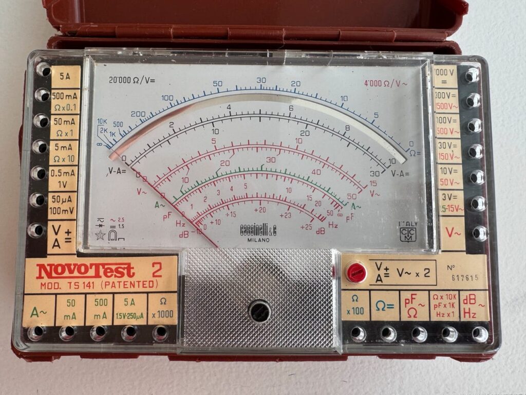
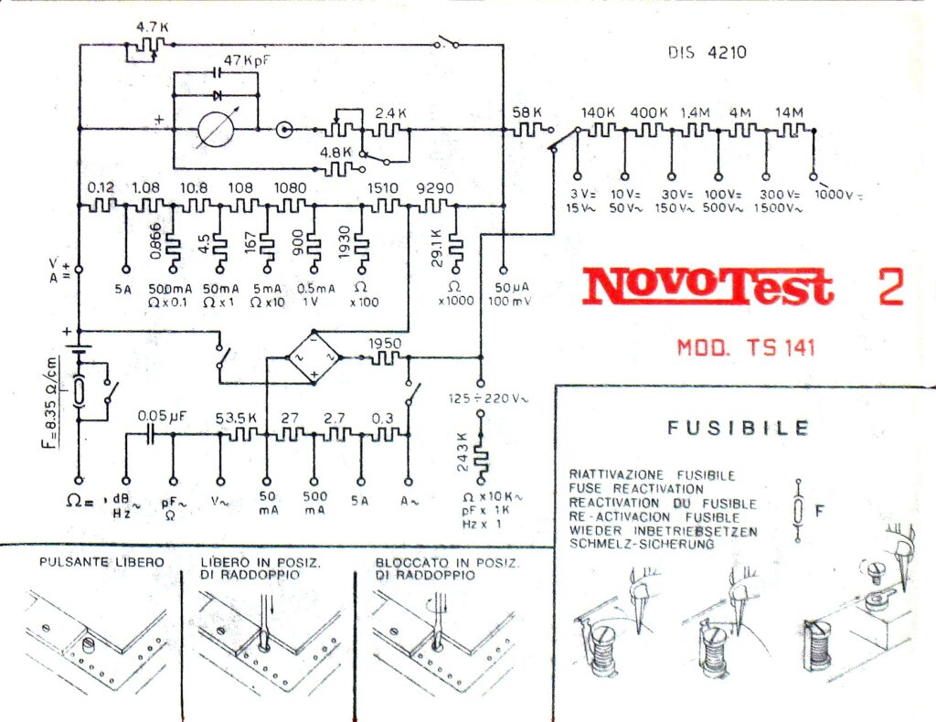
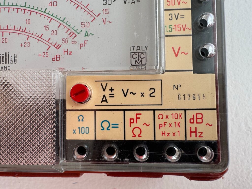
Examining the labels around the front-panel sockets, one notices that the 50 µA DC current input also serves as the 100 mV voltage-measurement range. With an instrument of this type, that is hardly surprising. From this alone one can immediately infer the sensitivity of the core meter movement: 100 mV / 50 µA = 2 kΩ. (The schematic shows a trimmer resistor in series with the movement, presumably for calibration, so the 2 kΩ should be understood as including that adjustment element.)
Studying the circuit diagram reveals another detail: the meter movement itself is protected against reverse polarity, but there is no fuse to protect it against overcurrent. One should keep this in mind before inadvertently burning the poor thing out. In the resistance-measurement section, the battery is placed in series with a fuse marked “F = 8.35 Ω/cm,” and in the corner of the schematic there is a small illustration showing how this device can be “reactivated.” It is presumably a mechanical thermal cutoff that can be reset rather than replaced.
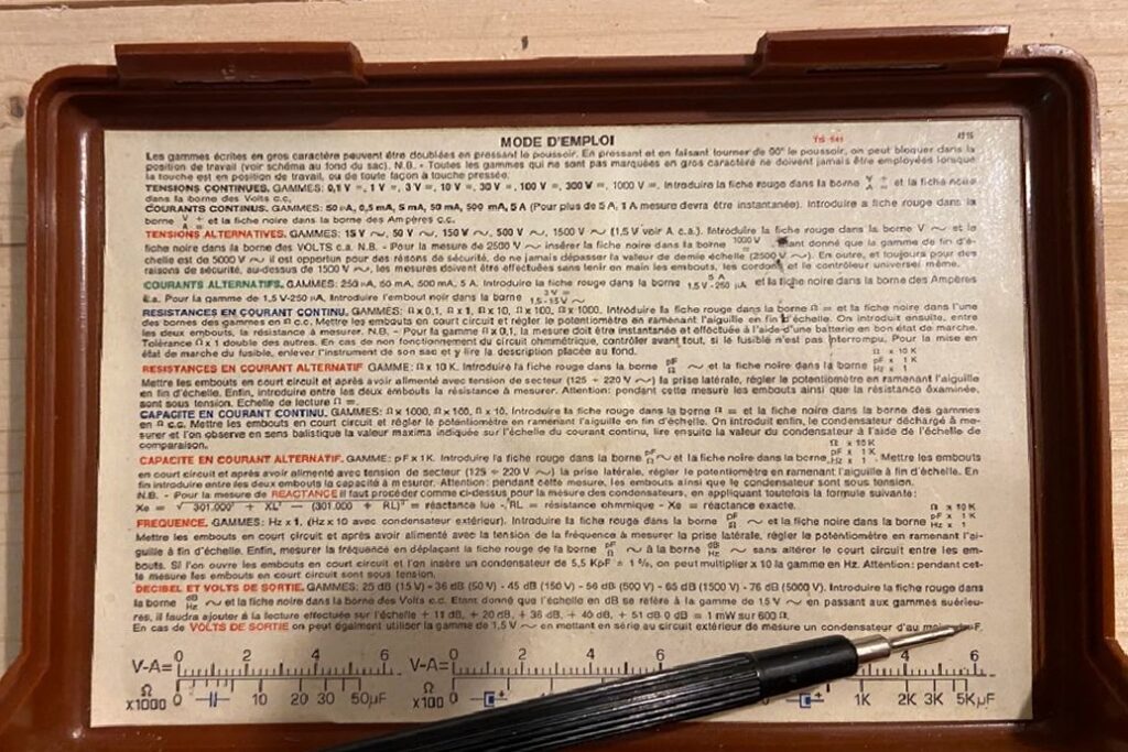
On the right side of the front panel there is a red, screwdriver-operated button labeled V/A ± = V~ ×2. When pressed, certain voltage (DC), current (DC), and AC-voltage ranges can be doubled. In the default position the slot is horizontal (–); once pressed, it can be locked by rotating it 90 degrees to the vertical ( | ). One must be careful, however: not every range may be doubled, and there are specific ranges where using this button is strictly prohibited.
The edge of the scale plate notes that the meter has an internal resistance of 20 kΩ/V on DC voltage ranges and 4 kΩ/V on AC ranges (as we will see, even these values are not universally true on every range). This means that the meter’s internal resistance depends on the selected range. For example, on the 10-V DC range it is 200 kΩ; on the 30-V range, 600 kΩ; on the 100-V range, 2 MΩ. In other words, it depends on the range, not the measured voltage.
An ideal voltmeter would draw no current at all—its internal resistance would be infinite—so it would not disturb the circuit under test. This instrument is very far from ideal: 20 kΩ/V is extremely low by modern standards. Contemporary digital multimeters typically present an input resistance of 10 MΩ, independent of range. Because of its relatively low internal resistance, this meter significantly loads the circuit being measured, thereby distorting the very quantity it is supposed to measure merely by being connected.
In older electrotechnical equipment this was not a problem: most circuit resistances were a few hundred or a few thousand ohms, making the loading effect negligible. But in vacuum-tube and later semiconductor circuits this was no longer acceptable, which is why the first high-impedance instruments—“vacuum-tube voltmeters”—appeared.
A meter like this one can still be perfectly serviceable for automotive electrical work, motor and relay circuits, and various household electrical measurements. It is, however, unsuitable for most measurements inside electronic devices. There are exceptions: checking button cells, AA batteries, or power-supply rails. In these cases a bit of loading is actually beneficial, ensuring that some current flows. Modern digital multimeters are often too sensitive for such tasks, giving wildly misleading readings—and in some cases showing a voltage even when the probe is barely making contact at all.
Measurement modes
DC Voltage Measurement
The red test lead is inserted into the V/A += socket, and the black lead goes into the V socket corresponding to the selected measurement range. Readings are taken from the V–A= scale.
Available ranges: 100 mV – 1 V – 3 V – 10 V – 30 V – 100 V – 300 V – 1000 V
On the smallest, 100 mV range, the minimum discernible DC voltage is approximately 2 mV.
The meter’s internal resistance is 20 kΩ/V, except on the 100 mV range, where it is only 2 kΩ/V.
All ranges can be doubled, except the 1000-V range, on which the manual explicitly forbids the use of the doubling button. According to the schematic, pressing the button will not actually damage the instrument, but even so, voltages above 1000 V must never be measured with it, regardless of button position.
DC Current Measurement
The red test lead is inserted into the V/A += socket, and the black lead goes into the A socket corresponding to the selected current range. Readings are taken from the V–A= scale.
Available ranges: 50 μA, 0.5 mA, 5 mA, 50 mA, 500 mA, 5 A
All ranges can be doubled, but for currents above 1 A (i.e., on the 5-A range), only momentary measurements are permissible to avoid overloading the instrument—continuous measurement is not. The meter has no fuse protection, so in the event of an overcurrent, the movement can burn out.
AC Voltage Measurement
The red test lead is inserted into the V~ socket, and the black lead goes into the V~ socket that corresponds to the selected range. Readings are taken from the V~ scale.
Available ranges: (1.5 V) – 15 V – 50 V – 150 V – 500 V – 1500 V
The 1.5-V and 1500-V ranges cannot be doubled; all others can.
The meter’s internal resistance is 4 kΩ/V, except on the 1.5-V range where it is 6 kΩ/V, and on the 1500-V range where it is 50 kΩ/V. The 1.5-V range shares its input socket with the 250 μA~ AC current range. Because AC measurements use direct diode rectification, the AC voltage and current functions are less sensitive, and the AC scales are non-linear. The smallest readable AC voltage is approximately 50 mV.
The instrument can measure up to 2500 V AC if the black lead is inserted into the “1000 V–” socket instead of the 1500 V~ socket. In this configuration, readings must be taken from the 0–50 V~ scale. On that scale, 2500 V corresponds to mid-scale, and full-scale deflection corresponds to 5000 V. For safety reasons, however, the 2500-V limit must never be exceeded.
Never perform measurements above 1500 V AC while holding the instrument, its test leads, or its probes in your hands.
AC Current Measurement
The red test lead is inserted into the A~ socket, and the black lead goes into the adjacent A socket corresponding to the selected measurement range. Readings are taken from the A~ scale.
Available ranges: 250 µA~, 50 mA~, 500 mA~, 5 A~
None of these ranges can be doubled. For currents above 1 A, only momentary measurements are permissible to avoid damage to the instrument. Continuous measurement at such levels must not be attempted.
DC Resistance Measurement
The black test lead goes into the Ω= socket, and the red lead into the Ω × X socket. The original manual states the opposite. I suspect the author assumed the usual convention in which the red lead is positive and the black negative—but in many meters, the polarity is reversed during ohmmeter operation. Functionally it makes no difference; the important point is simply to remember that Ω= is the negative pole in this mode.
This is the only function that requires the internal dry cell; all other measurements can be made without a battery. The usable range is roughly from 0.1 Ω to 200 kΩ (and with considerable charity, up to 10 MΩ), but—as the scale clearly shows—the response is very non-linear, making the higher values difficult to read. This is inherent in the measurement principle and entirely typical of instruments of this type. For this reason, the manual does not list “ranges” in the usual sense but rather multiplier factors for the common scale.
Because the battery voltage changes over time, the meter must always be zeroed before measurement: short the test leads together and adjust the potentiometer on top of the instrument until the pointer reaches full-scale. (Note that the Ω scale is reversed: full-scale corresponds to zero ohms.)
Multipliers: ×0.1 – ×1 – ×10 – ×100 – ×1000 Ω
Accuracy: The ×1 and ×10 ranges have an accuracy of ±2× compared with the others.
Note: If the ohmmeter does not function correctly, check the battery and the fuse first. The ×0.1 Ω range requires rapid measurement because the battery condition changes quickly under load, which affects the reading.
AC Resistance Measurement
The instrument can also be used to estimate AC resistance on a single range: Ω × 10k, covering approximately 0…5 MΩ.
On the side of the meter there is a mains connector that allows the device to be powered from a 125–220 V AC supply. The red lead goes into the Ω × 10k socket, and the black lead into the pF Ω~ socket. First, the test leads must be shorted together; only after that should the instrument be connected to the mains. Then adjust the potentiometer to bring the pointer to full-scale. Once zeroed, resistance measurement can proceed.
During measurement, do not touch the test leads or the component under test. The leads are not connected directly to the mains but through large-value resistors; muscle spasm or fatal electric shock is unlikely, but a distinctly unpleasant jolt is still possible if the Ω~ lead is touched.
For the sake of our non-technical friends who are still holding up over coffee: AC resistance (also called impedance—so that the apprentice bakers don’t understand it) expresses how much a component “hinders” the flow of alternating current. A simple resistor always hinders current to the same extent, but a coil does not. A coil offers almost no hindrance to direct current, since it is essentially just a length of wire wound into a shape. For example, the DC resistance of an electric motor’s windings is one or two ohms (you can measure this with any modern digital multimeter). Yet the motor will not conduct hundreds of amperes when connected to the mains, even though—based on Ohm’s law and the measured resistance—that is exactly what one would expect. The reason is that the coil’s AC resistance is far higher. And this resistance is frequency-dependent: the higher the AC frequency, the higher the impedance.
For capacitors it is just the opposite: a capacitor is an insulator between two conductors, so direct current does not flow through it—its DC resistance is effectively infinite. But AC does pass through it, and the higher the frequency, the more easily it flows.
Impedance itself is a somewhat more elaborate concept: its value cannot be handled properly with ordinary real numbers; we normally use complex numbers to describe it. This instrument allows you to estimate the magnitude of the impedance at 50 Hz, but it provides no information about the associated phase angle.
Capacitance Measurement – Using Direct Current
A closer look at the front panel reveals that this device can also measure capacitance. The manual states that two different measurement methods are available; the first is a DC method, which uses the internal dry cell.
Before measurement, the capacitor must be fully discharged. Any residual charge will distort the reading and may damage the instrument.
Measurement ranges: 50 µF – 500 µF – 5000 µF
The red test lead is inserted into one of the Ω × 1000, Ω × 100, or Ω × 10 sockets, and the black lead into the Ω= socket (the manual reverses them, but Ω= is in fact the negative pole).
With the test leads shorted, set the pointer to full-scale using the potentiometer exactly as in resistance measurement. Then connect the capacitor to the test leads (for electrolytic capacitors, the negative terminal goes to Ω=). Using the V–A= scale, read the maximum pointer deflection; then use the auxiliary scale printed inside the instrument’s lid—corresponding to the chosen range—to determine the capacitance value.
Capacitance Measurement – Using Alternating Current
Range: pF × 1K
Insert the red test lead into the pF Ω~ socket and the black lead into the pF × 1K socket. The instrument must be connected to the mains (125–220 V AC) for this measurement. Because the probes and the capacitor under test are live during operation, extra caution is required.
Readings are taken from the pF scale, and the measurable capacitance range is 0…50 nF.
Note: When measuring reactance, the procedure is similar to AC capacitance measurement, but the following formula must be used:
X_e = \sqrt{301{,}000^2 + X_L^2 - (301{,}000 + R_L)^2}
where:
• Xe is the exact reactance we wish to calculate,
• RL is the ohmic resistance (the loss resistance of the coil or capacitor),
• XL is the reactance value read from the scale.
Explanation:
Let R₀ = 301,000 Ω, the meter’s internal series resistance on this range. The pointer deflection depends on the absolute value of the current (|I|), which in turn depends on the magnitude of the total impedance (|Z|). The scale is calibrated as if there were no loss resistance at all:
|Z_{\text{cal}}| = \sqrt{R_0^{2} + X_L^{2}}.
If the coil or capacitor does in fact have an ohmic loss resistance R_L, then the total impedance “tilts” in the complex plane, and the value X_L read from the scale is no longer the true reactance:
|Z_{\text{actual}}| = \sqrt{(R_0 + R_L)^{2} + X_e^{2}}.
The meter’s pointer will reach the same deflection whenever the current is the same, therefore:
|Z_{\text{cal}}| = |Z_{\text{actual}}|,
which gives:
\sqrt{R_0^{2} + X_L^{2}} = \sqrt{(R_0 + R_L)^{2} + X_e^{2}}.
Squaring both expressions allows us to solve for the exact reactance:
X_e^{,2} = R_0^{,2} + X_L^{,2} - (R_0 + R_L)^{2}.
Substituting R₀ = 301,000 Ω yields precisely the formula given in the manual.
It is important to note that for both capacitors and inductors, the Rₗ loss resistance that appears in the formula is not the same as the resistance you can measure in DC ohmmeter mode. Both manifest as ohmic (purely real) components of impedance and both cause power loss, but they describe entirely different physical phenomena.
For an inductor, the DC resistance (DCR) is simply the ohmic resistance of the winding wire, determined solely by the material, length, and cross-section of the conductor:
\mathrm{DCR} = \rho \cdot \frac{l}{A}
Typical values range from a few milliohms to a few ohms.
The loss resistance (ESR), however, is frequency-dependent and includes contributions from skin effect, hysteresis losses, eddy-current losses, dielectric losses of insulation, and more. Typical values range from a few hundred milliohms to tens of ohms.
For a capacitor, the DC resistance is dominated by the leakage resistance—a large-value resistor (10 kΩ to 100 MΩ or even higher) that can be modeled as a parallel resistance across the capacitor.
The capacitor’s ESR appears as a series resistance and arises partly from genuinely series ohmic elements (lead resistance, foil electrode resistance), but largely from dielectric losses such as dipole relaxation, hysteresis, and dielectric absorption. These effects are strongly frequency-dependent, and typical ESR values are on the order of a few tenths of an ohm.
Frequency Measurement
Range: Hz × 1 (and Hz × 10 with an external capacitor)
Insert the red test lead into the pF Ω~ socket and the black lead into the Hz × 1 socket—exactly as in AC-capacitance measurement. Connect the instrument to the mains and use the potentiometer to set the pointer to full-scale. Then measure the frequency by moving the red lead from the pF Ω~ socket to the Hz~ socket. Do not change the circuit under test while doing this.
In this configuration, the instrument measures frequencies in the 0–50 Hz range.
If a 5500 pF ±1% external capacitor is inserted in series with the red lead, the scale is multiplied by ten, and the instrument can measure frequencies in the 0–500 Hz range.
Output Level (Decibel) Measurement
Ranges: 25 dB (15 V), 36 dB (50 V), 45 dB (150 V), 56 dB (500 V), 76 dB (1500 V)
Reference: 0 dB = 1 mW into 600 Ω
The red test lead is inserted into the dB~ socket, and the black lead into the appropriate V~ socket. On the 15-V AC range, the output level in decibels can be read directly from the dB scale.
Because the dB scale is calibrated specifically for the 15-V range, measurements made on the higher ranges must be corrected by adding the appropriate offset:
• +11 dB for the 50-V range
• +20 dB for the 150-V range
• +36 dB for the 500-V range
• +51 dB for the 1500-V range
Additional Accessories
A shunt module (type SH30) was available for the instrument, enabling current measurements up to 30 A, as well as a current transformer that allowed the meter to measure up to 200 A AC.
Under the type designation VC150, a high-voltage probe was sold for the instrument, making it possible to measure voltages up to 25 kV.
Other optional accessories included the L1N photocell, which enabled light-intensity measurements up to 20,000 lux, and a thermocouple probe for temperature measurement in the –25 to +250 °C range.
Our friends in Milan truly extracted every last bit of functionality from this little instrument. In the early 1980s they even released an improved version under the designation Novotest 3 TS162. Its technical specifications and capabilities were essentially identical to those of the Model 2, but instead of using a single 3-V 2R10 dry cell, it operated on two 1.5-V AA batteries.