Among radio amateurs – especially abroad – fox hunting is still a fairly popular sport today. Here I present a simple fox‑hunting setup that can be used at home, in the garden, for play, for tracking animals, or even for hunting “flying foxes”.
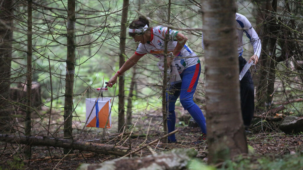
“Fox hunting”, or radio orienteering (Amateur Radio Direction Finding – ARDF, also known as “Fox Hunting” or “T‑Hunting”), is a popular sport among radio amateurs in the United States, Australia, and Asia as well. It is a fantastic “hybrid” sport: it simultaneously requires physical endurance, map‑reading skills, and technical aptitude in handling a radio receiver.
The 2025 World Championship was held in Birštonas (Lithuania) in August; the 2024 event took place in Primorsko on the Bulgarian Black Sea coast, and the South Korean postal service even issued a commemorative stamp for the 2018 World Championship in Sokcho‑si. Since this is a niche sport, the most up‑to‑date information and the community itself can best be reached through national associations and dedicated discipline‑specific websites.
If you are interested in fox hunting
If you are interested in the sport, start with the ARDF pages of IARU (International Amateur Radio Union) Region 1. At present this is the most active and informative site. You will find excellent downloadable regulations, technical descriptions, and a global event calendar.
The best tutorial site for beginners is HomingIn.com, the website of Joe Moell (K0OV), the “encyclopedia” of the sport. It offers a “Getting Started” guide, descriptions of receiver construction, and even tips for teachers on how to introduce the sport to young people. Although the design is “retro”, the content is invaluable.
ARDF (DARC): a comprehensive hub for ARDF news, events, and international competition information. It is ideal for beginners to see the sport’s competitive landscape.
OpenOrienteering.org: Map reading is essential for radio orienteering, but the resources here are equally valuable for everyday hikers and outdoor enthusiasts. The site offers free software (Mapper) and clear guides for understanding and using maps, making it useful well beyond radio sports.
In Hungary there are also competitions; those interested can find information at Hungarian Radio Direction Finders Website.

Fox hunting in a nutshell
The “foxes” are hidden radio transmitters placed in the forest. In adult competitions the course length is typically 6–8 km, and in addition to the finish transmitter there are 4–5 active transmitters. The competitors’ task is to find these in the shortest possible time (30–45 minutes), using an orienteering map and a special direction‑finding receiver.
In the early heroic days of radio, the “fox” was literally a radio operator sitting in a bush or up in a tree, manually operating a transmitter the size of a shoulder bag. Today the transmitters are automated and barely larger than a soapbox.
The 80‑meter shortwave band (HF, 3.51…3.60 MHz) and the 2‑meter VHF band (144…145 MHz) are separate competition categories – they require different equipment and methods due to the different propagation characteristics of radio waves. HF receivers are simpler, cheaper, and smaller; for beginners HF is recommended. On VHF the task is more difficult, mainly because reflections from terrain objects are disturbing, and the closer you get to the transmitter, the worse the situation becomes. VHF receivers are larger, more expensive, and more complex.
On VHF, some variant of a dipole antenna is usually used. A common choice is the Yagi antenna, invented in 1926 at Tohoku University by Dr. Hidetsugu Yagi and Dr. Shintaro Uda. This is essentially a simple dipole supplemented with parasitic elements. Most old television antennas seen on rooftops are also of this type. With this antenna, reception is strongest when the boom of the antenna points toward the transmitter. The more elements and the longer the Yagi, the higher the gain and the sharper the directivity. However, in the forest the antenna cannot be too large, so fox hunters typically use only 3–4‑element Yagis, which have a wide beamwidth (40–60 degrees) and a relatively poor front‑to‑back ratio. Accurate bearings are therefore difficult.
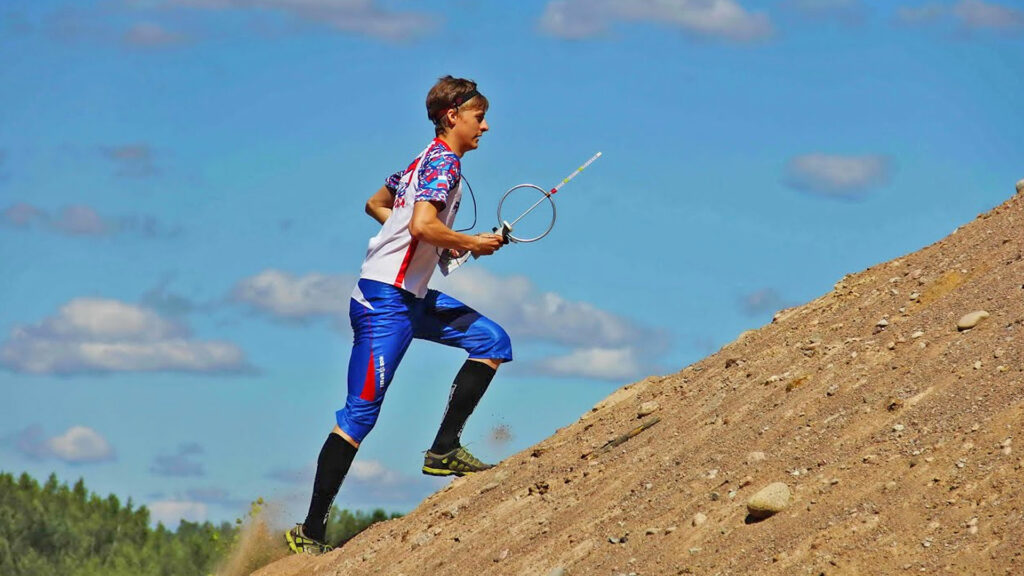
A professional VHF direction‑finding receiver costs around 400 euros. It is no surprise that many people nowadays use inexpensive Chinese walkie‑talkies for this purpose (e.g. Baofeng UV‑5R, Quansheng UV‑K5, etc.). This is not a professional solution, but when fitted with a simple loop antenna, they can be used for direction finding. With a loop antenna, one does not look for the strongest signal, but for the weakest one; this null can be found with an accuracy of about 10 degrees. The transmitter then lies perpendicular to that direction. The drawback is that the antenna sensitivity is low, and it cannot distinguish between the forward and backward directions.
There is another method for radio direction finding: localization based on time differences (Time Difference of Arrival – TODA). This method is very accurate and is therefore used, for example, for wildlife tracking or for indoor navigation of warehouse robots. In fox hunting it has not become widespread so far, because it requires multiple antennas and digital signal processing. Recently, Joe Leggio (WB2HOL) from North Carolina – long known for his work on fox‑hunting equipment – came up with a simple solution. The device presented here is based on his idea. All it requires is a wooden slat or broom handle, a few thin metal rods or knitting needles, a handful of small components, some coaxial cable, and a suitable walkie‑talkie.

A “shotgun” for radiosondes
When searching for fallen meteorological radiosondes, several methods are available. One of them – although certainly not the fastest or most efficient, but technically interesting and challenging – is direction finding.
With conventional fox‑hunting direction‑finding receivers it is difficult to work close to the transmitter because of reflections. The very simple and inexpensive device presented here has the special advantage that it can be used accurately at distances of only a few meters, yet it also works from tens or even hundreds of kilometers away.
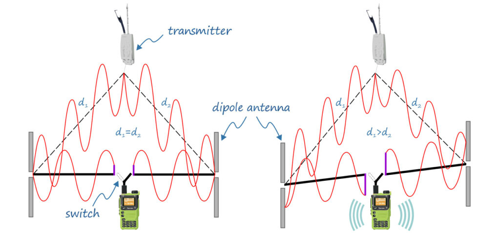
The trick is that it uses two dipole antennas, which are mounted at the two ends of a wooden rod. Imagine that the two dipoles are exactly the same distance from the transmitter. This occurs when the transmitter lies on the perpendicular bisector of the rod. In this case both antennas deliver identical signals. If we alternately switch the two antennas to the receiver using a switch, nothing interesting happens: the signal remains the same, and the receiver does not detect the antenna switching.
Now rotate the broom handle. The distances of the two antennas from the transmitter change, so the radio wave reaches one antenna slightly earlier than the other. In other words, the two antennas deliver signals with different phases. As a result, a click is heard in the receiver every time the antenna is switched.
If we build an electronic switch that alternates the antennas at an audio frequency (600–1200 Hz), then instead of clicks a continuous tone will be heard in the receiver.
Note that only a small distance difference is required. At 400 MHz the wavelength is about 75 cm, so a difference of just 10–15 cm already matters significantly – and this is independent of the absolute distance.
The dipoles can be made from 6 mm aluminum tubing or even from metal knitting needles. The length of the rods is one quarter of the wavelength; for radiosondes (operating between 400 and 406 MHz) this is about 18 cm. For other frequencies different dimensions are required, but everything else remains the same.
The device is not sensitive to exact component values, nor to dimensions (except for the dipole length). However, symmetry is important: the dipoles must be connected to the central switching unit with coaxial cables of identical length (RG‑58). Otherwise the receiver will give a biased bearing.
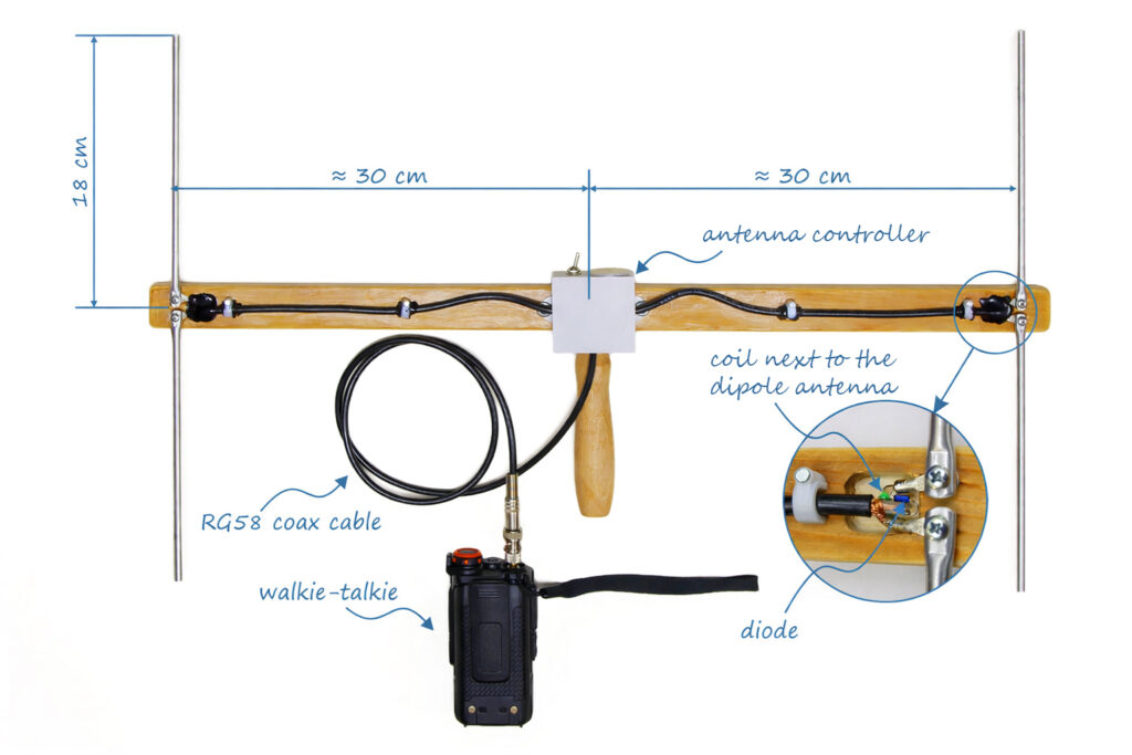
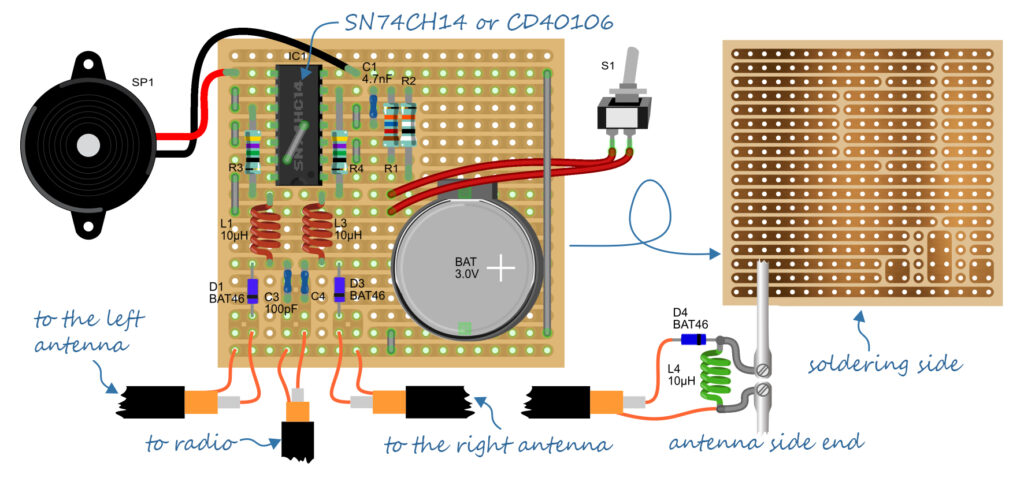
The heart of the device is formed by the switching diodes. I used small‑signal Schottky diodes of type BAT46 (because I had them at hand), but any fast small‑signal diode will do. As can be seen in the photos, one diode is mounted directly at each dipole, and two more are located in the switching unit according to the schematic.
Next to each diode there is also a small 10–15 µH inductor to separate the audio‑frequency control signal from the RF signal.
In the center, inside the gray box, is the controller. A low‑cost SN74HC14 (or SN74HC04, CD40106, CD4069) integrated circuit, wired in a standard oscillator configuration, generates two anti‑phase audio‑frequency square waves. Since one inverter in the IC remained unused, I also fed the signal to it and connected a piezo buzzer to its output. This is optional, but useful, as it provides a quiet beep indicating that the device is switched on.
The device consumes very little current and can run for a long time from a button cell. I do not provide a formal schematic; based on the photos it is not difficult to build the device anyway.
Fox hunting in the garden
If you want to play fox hunting at home, with friends or in a school club, you can buy 433 MHz RF modules for about 500 HUF. These are commonly used in weather stations, alarms, gate openers, etc. All that is needed is a 6–9 V battery, and the fox transmitter is ready.
These modules have an output power of 10 mW and do not require a transmitting license, which is more than sufficient for an area the size of a football field. Those with some programming skills can control them with, for example, an Arduino Mini module, allowing several fox transmitters with different codes to operate simultaneously, just like in real competitions.
The presented “broom‑handle gun” can also be used to search for such transmitter modules without any modification; only the dipole lengths should be adapted to the 433 MHz frequency. In this case the four λ/4 rods should each be approximately 166 mm long if made from 6 mm aluminum tubing.
Once the receiver is ready, the transmitters are prepared, and the weather is good, the game can begin. Good luck!
Note: The dipole length is only nominally one quarter of the wavelength (λ/4). According to the laws of physics, radio waves propagate at the speed of light in a vacuum (and to a very good approximation in air as well). However, when the wave travels along a metal conductor (antenna), it interacts with the atoms of the metal and the surrounding insulating materials. This interaction slows down the wave. Because the wave is slower, the wavelength corresponding to a given frequency is shorter in the conductor than in free space. When designing antennas, this effect is taken into account by the so‑called velocity factor (shortening factor). The theoretical dimensions are simply multiplied by this factor, and since k < 1, the practical antenna will be smaller.
In our case the velocity factor differs only slightly from 1, so our antennas will be only a few percent shorter. The exact value depends on the thickness and material of the antenna and on whether it is insulated (e.g. bare metal conductor: k ≈ 0.95…0.98; insulated wire: k ≈ 0.90…0.95; coaxial cable: k ≈ 0.66…0.85). If rods of a different diameter are used (or the antenna is designed for a different frequency), the dimensions can be calculated while taking the shortening into account using, for example, the Straight Dipole Calculator (https://www.changpuak.ch/electronics/Dipole_straight.php).