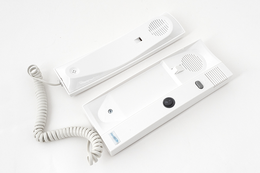
The DP–2 digital intercom indoor units are widely used. They are compatible with the Codefon intercom systems commonly found in Hungary, and their circuitry is completely identical to the Codefon EVK apartment handset. On some versions, an external doorbell button can also be connected, and there is an option for an external loudspeaker output, which is particularly helpful for elderly users. For elderly people—who often have difficulty hearing higher frequencies—a lower-pitched sound panel is also available. This device is simple, inexpensive, and generally trouble-free.
That is, until a puppy, a kitten, or a baby arrives in the household. At that point, the problem becomes obvious: the unit signals both ringing and door release with a sharp, high-pitched beeping sound that easily startles the little ones in the household.
Several people have already asked me how this could be quietened. So let us take a look at the circuit diagram.
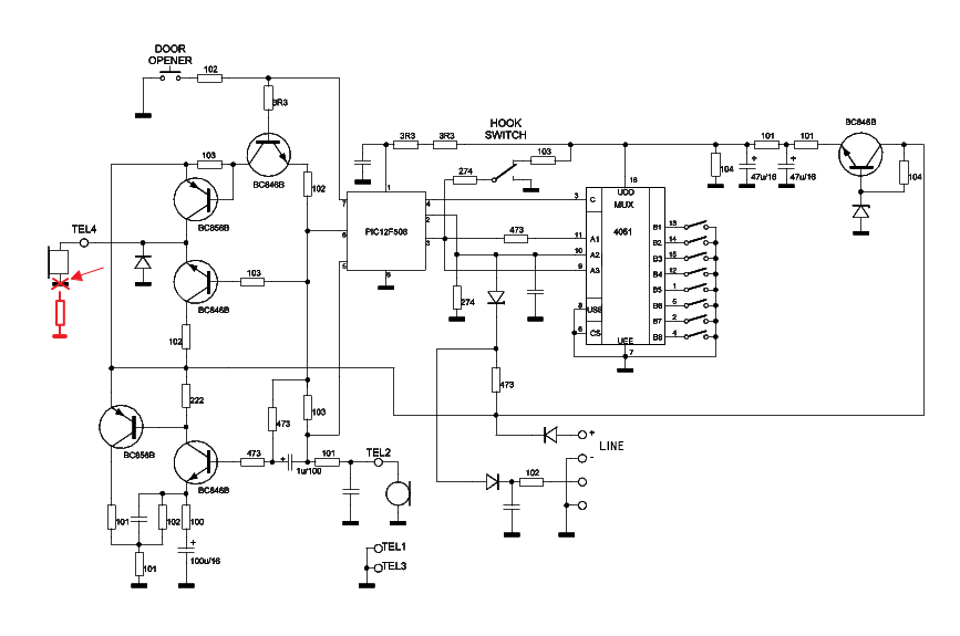
The ringing signal originates from the PIC12F508 microcontroller and is fed to the loudspeaker located in the handset. The sound level of the speaker can be significantly reduced by simply wiring a 1.0…1.5 kΩ resistor in series with it, at the point indicated on the circuit diagram. However, the ideal solution would be to reduce only the beeping and whistling tones, without attenuating the speech audio. It would also be useful if the attenuation could be switched on and off.
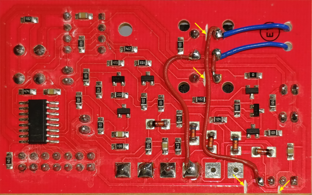
Fortunately, the hook switch is a double-pole, double-throw (DPDT) switch, and one of its terminals is connected to ground—as can be seen in the circuit diagram. There it is shown as a single switch, but in reality, on the PCB, the two switch sections are simply wired in parallel. One half of this switch can therefore be used to bypass the resistor when the handset is lifted. On the printed circuit board, the tracks must be cut at the four locations marked with yellow arrows in the photograph. Then, the three jumper wires shown in the picture must be soldered in place—one to restore the interrupted ground track, and two other to reconnect the loudspeaker.
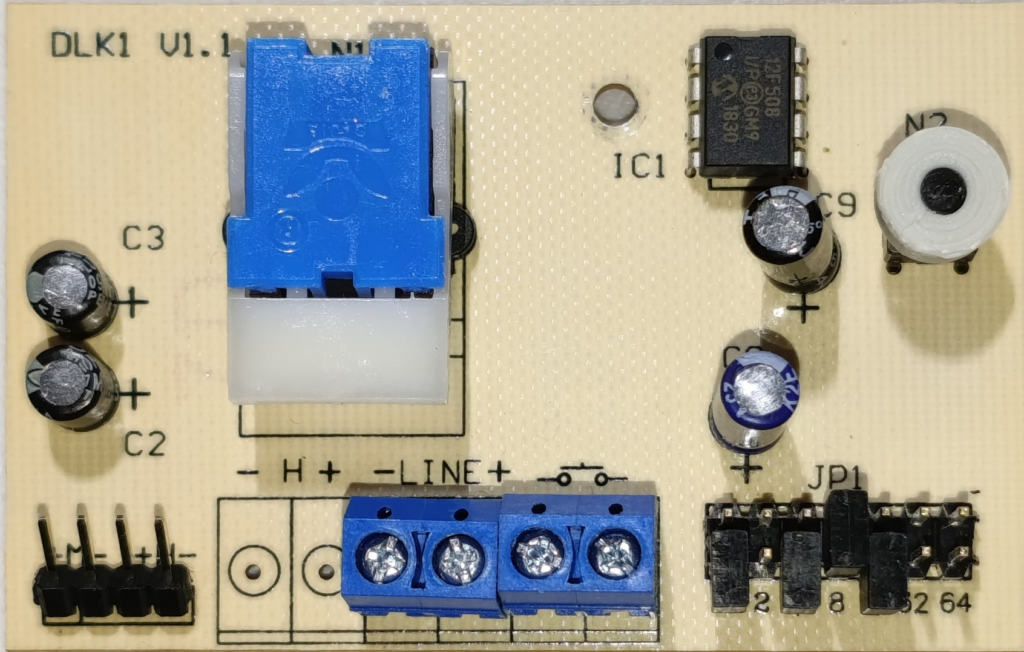
After that, solder two additional wires to the hook switch, as shown in the picture. The other ends of these wires are connected to a switch mounted on the front panel. The resistor is also soldered to this front-panel switch, as shown below.
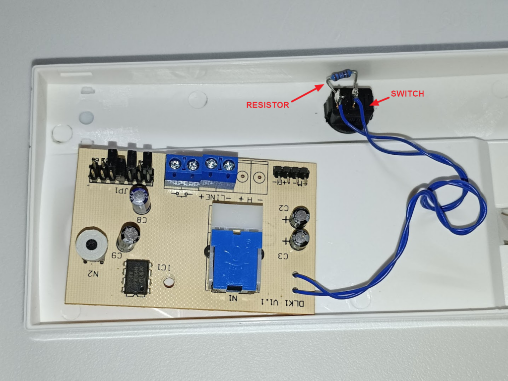
Operation
- If the front-panel switch is turned on, the loudspeaker receives ground directly through it—everything works exactly as it did originally, with no attenuation.
- If the front-panel switch is turned off and the handset is on the cradle, the loudspeaker receives ground through the resistor, and the sound is attenuated.
- When the handset is lifted, the hook switch changes over and provides a direct ground connection to the loudspeaker. In this case, there is no attenuation or muting at all—the unit operates exactly as originally intended, and conversation is fully audible.
Note: If the resistor is omitted altogether, the loudspeaker will be completely silent when the front-panel switch is open and the handset is on the cradle.
Instead of using a front-panel switch, the resistor can also be permanently wired in by soldering it directly to the hook switch. In that case, the intercom will always ring quietly, with no way to disable the attenuation.
Another option is to replace the switch and resistor with a miniature switched potentiometer. This would make the volume adjustable. In my opinion, however, this offers little practical benefit.