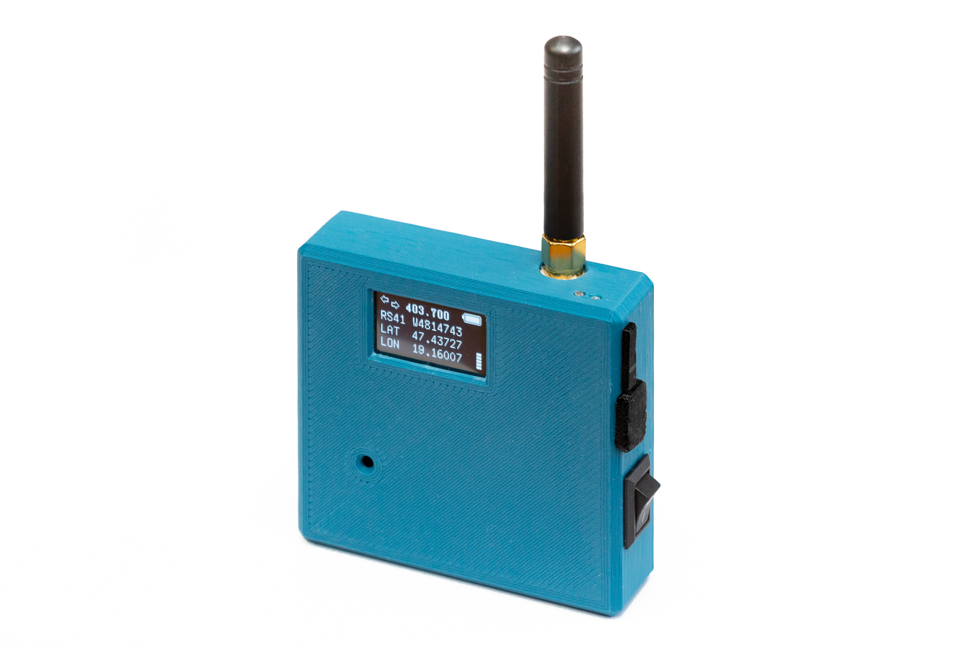
Radiosondes fall back to Earth every day. Most people never notice them. With a small, purpose-built receiver like the MySondy Go, you can not only notice them, but actively track, decode, and recover them. This article documents our build of a MySondy Go device, including a custom-designed 3D‑printed enclosure optimised for real-world field use.
Why Radiosonde Hunting Is So Fascinating
Weather balloons carrying radiosondes are launched worldwide, often twice a day, by meteorological services. These radiosondes transmit telemetry data — position, altitude, temperature, humidity — while ascending to the stratosphere. After the balloon bursts, the sonde descends — often, but not always, by parachute — and continues transmitting until it lands.
Radiosonde hunting (also known as radiosonde tracking) combines radio engineering, software-defined radio, navigation, and a bit of outdoor adventure. With the right hardware and open-source software, it becomes possible to receive these signals directly, decode them in real time, and even locate the fallen sonde. The MySondy Go project was created exactly for this purpose: a compact, self-contained tracker built around widely available components and open software.
Building the Electronics
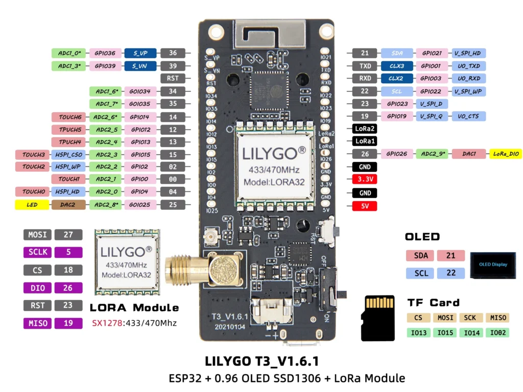
The MySondy Go is based on the TTGO LoRa32 platform, an ESP32-based development board that integrates a LoRa transceiver, OLED display, microSD card slot, and USB interface in a single compact module. The official project description, firmware, and documentation are maintained on the MySondy Go project page and its associated GitHub repository:
- Project website: https://mysondy.altervista.org/mysondygo.php
- Source code and firmware: https://github.com (MySondy Go repository)
Following the official documentation, the electronics assembly itself is straightforward:
- TTGO LoRa32 board as the core controller and RF frontend
- SMA antenna connector for external antennas
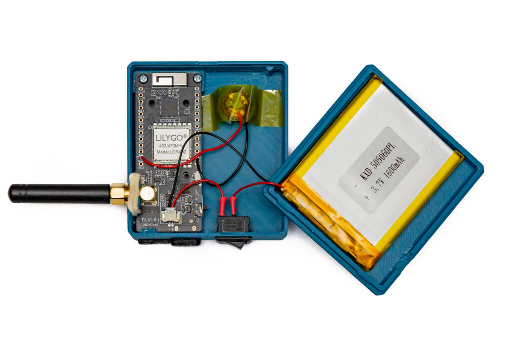
- Li‑Po battery for standalone operation (650–1000 mAh is usually sufficient; we used a 1600 mAh cell simply because it was available. Any Li‑Po battery of approximately 50 × 60 × 5 mm fits the housing.)
- Piezo buzzer for acoustic feedback and alerts
The firmware is flashed according to the instructions in the MySondyGO_Manual_EN.pdf provided on the project website. In our case, installation was done using Espressif’s flash_download_tool_3.8.7. Since CH341 USB–serial drivers were already installed from earlier projects, the TTGO LoRa32 was recognised immediately (the driver is also included in the MySondy package).
During flashing, the ChipType must be set to ESP32, while WorkMode can remain at the default develop setting. After the firmware upload has completed, the device must be restarted using the RST button. Once installed, the device is able to scan, receive, and decode multiple types of radiosonde signals. The microSD card slot provides removable storage (exact logging support depends on the firmware/app version), while the OLED display provides immediate visual feedback in the field.
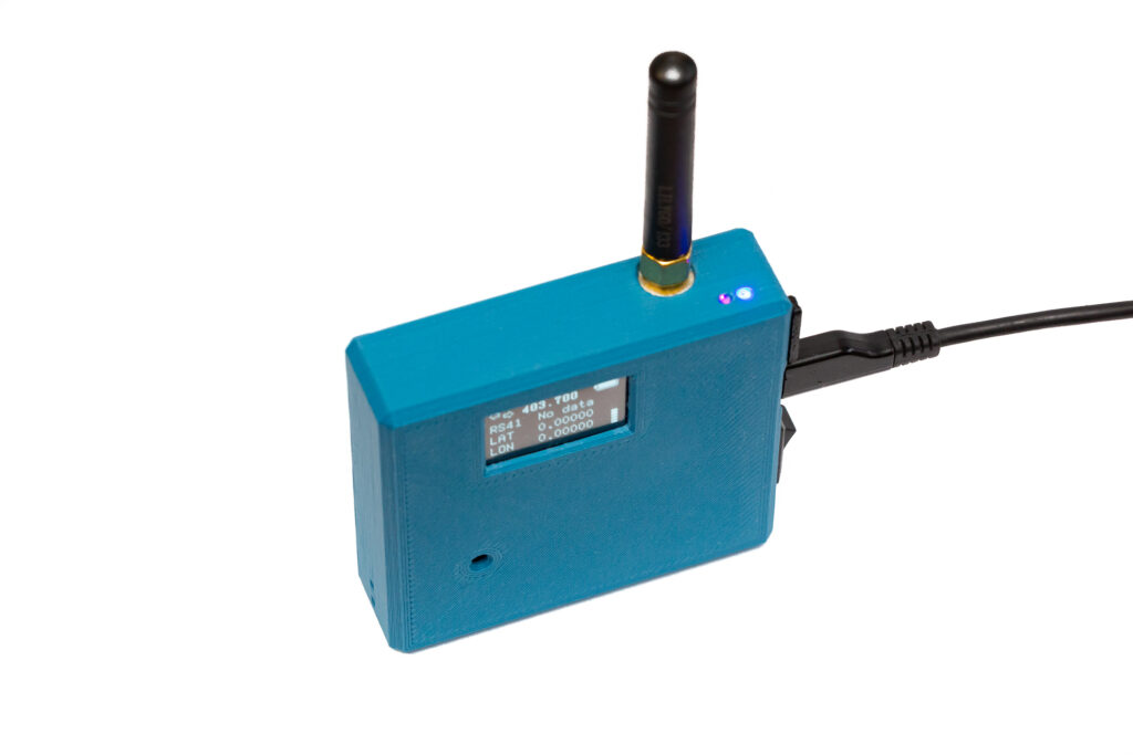
In our build, particular care was taken to ensure that all connectors remain accessible: the USB port for charging and firmware updates, and the microSD card slot for data access. This allows the device to be used and maintained without opening the enclosure.
You can get support for the project via the forums where discussions are in English, albeit the project seems especially popular in Italy since that’s where the developers are based.
LILYGO MySondy GO LoRa32 specifications
The Lilygo TTGO LoRa32 is a development board for LoRa applications baesed on the ESP32-PICO-D4.
- SiP – Espressif Systems ESP32-PICO-D4 system-in-package with ESP32 dual-core Xtensa processor @ 240 MHz, 2.4GHz Wi-Fi and Bluetooth 4.2 dual-mode, 4MB flash
- LoRa module – LORA32
- RF Transceiver – Semtech SX1268 connected over SPI to the ESP32 SiP
- Frequency – 433 MHz (The T3 board has options for 868 and 915 MHz, which I suspect are not suitable for radiosondes)
- Tx Power – Up to +14 dBm
- Rx current – 9.9mA
- Storage – MicroSD card slot
- Display – 0.96-inch OLED with 128×64 resolution (SSD1306 I2C display driver)
- Expansion – 2x 13-pin GPIO header with UART, SPI, I2C, VP/VN, ADC, DAC, TOUCH, LoRa1/2, and 5V, 3.3V, and GND power signals
- Misc
- Antennas
- 3D antenna for WiFi/BLE
- SMA antenna connector for LoRa
- Battery switch
- Reset and Boot buttons
- Antennas
- Power Supply
- 5V via USB-C port
- 3.7V LiPo battery support
- Dimensions – 66 x 36 x 15 mm
Designing and Printing the Enclosure
While the reference design focuses primarily on the electronics, we decided early on that a robust enclosure was essential for practical field use. The result is a custom-designed 3D‑printed housing tailored specifically to the MySondy Go.
Key features of the enclosure:
- Dustproof construction suitable for outdoor use
- Integrated compartment for a 1600 mAh Li‑Po battery
- Internal mounting for the buzzer
- Accessible USB connector and microSD card slot
- Flexible TPU dust cover protecting the connectors
- Felt dust seal around the SMA antenna connector
- Protective film in front of the OLED display, fixed with a thin double‑sided adhesive tape frame
- Two tiny indicator holes for onboard red/blue LEDs, plus two small side holes for threading a wrist strap
The main body of the enclosure was printed from a rigid filament, while flexible TPU was used for the removable dust cover.
Attach the battery to the back cover with soft double-sided adhesive. Make sure the battery cable is routed without strain and cannot be pinched when closing the enclosure; leaving a small service loop helps prevent long-term cable fatigue.
The onboard power switch of the TTGO module should be left in the ON position at all times. For power control, we added an external miniature KCD11-2P toggle switch, which proved to be mechanically more durable.
Making the LEDs Visible: Simple Light Pipes
The TTGO board has red and blue status LEDs, but enclosing the module normally hides this visual feedback or requires large openings that let dust in.
We solved this with a simple and effective trick: two small holes were placed in front of the LEDs, and 3–4 mm pieces of clear 1.75 mm nylon 3D-printing filament were glued in as light pipes. This guides the LED light to the surface, making the power and charging status clearly visible even in daylight.
Using the MySondyGo Mobile App
The handheld is controlled from the MySondyGo smartphone app, which connects to the TTGO over Bluetooth and provides the main user interface (settings, status, maps).
- Android: https://play.google.com/store/apps/details?id=org.mysondy.altervista.mysondygo
- iPhone: https://apps.apple.com/it/app/mysondy-go/id=6744840307
A concise setup flow (based on the English manual):
- Install the app, grant the requested permissions, and allow Bluetooth.
- Power up the MySondy Go and connect to the TTGO from the app (you’ll be asked to authorise the pairing the first time).
- Set reception parameters: press SET to enter the frequency, then NEXT to choose the radiosonde type, and finally SEND to push the new settings to the TTGO.
Don’t Skip Calibration: TUNE
After installation, the most important step is tuning/calibration. TTGO boards are typically a few kHz off-frequency, and the firmware’s receive bandwidth (especially for RS41) can be narrow enough that this matters.
With a moderately strong signal available — for example, a sonde in flight at ~40–50 km distance can be sufficient if you have decent antenna placement and (ideally) line-of-sight — go to the TTGO settings and press TUNE. The app scans a 500 kHz window around the currently set frequency, finds a useful signal, fills in the required offset, and then you simply press SAVE. (While receiving, the current correction value is shown in parentheses; small fluctuations are normal.)
Battery Gauge: Check BAT TYPE
Also verify the BAT TYPE setting. This has no effect on charging — it only influences how the percentage indicator is calculated.
- 0 (Linear): assumes voltage and capacity are proportional. With LiPo packs this often looks wrong (it can sit at 100% for a long time, then drop rapidly and die “suddenly”).
- 1 (Sigmoid / S-curve): recommended for typical modern LiPo / Li-ion cells. These batteries don’t discharge linearly: voltage drops slowly at first, then falls much faster near the end.
- 2 (Asigmoid): for special cells or custom discharge curves; usually unnecessary for standard TTGO + LiPo builds.
Buzzer: Set BUZ = 4 (GPIO4)
If you want the buzzer to actually sound, make sure the firmware/app setting BUZ matches the GPIO pin you wired it to. On the common TTGO LoRa32 builds the buzzer is on GPIO4, so set BUZ = 4 in the settings.
Small Quality-of-Life Detail: CALL
In the CALL field you can enter your callsign or a nickname — this will be shown on the TTGO display at startup.
Antenna
The device comes with the standard 433 MHz TTGO antenna, which results in a very limited range on the 400–406 MHz frequencies used by most radiosondes. The PDF manual includes a guide on how to modify this antenna for ~403 MHz. Even better, you can create a custom-built quarter-wave monopole antenna. Alternatively, for direction finding, you can use a Moxon, Yagi, or HB9CV antenna.
Conclusion
For anyone interested in radio, atmospheric science, or simply building a specialised instrument with a clear purpose, the MySondy Go is a highly rewarding project — and every successful sonde recovery makes the effort worthwhile.
The STL files required for printing the enclosure can be downloaded from:
https://www.printables.com/model/1576577-mysondy-go-a-pocket-tool-for-radiosonde-hunting