I wanted a simple, inexpensive antenna for my Little Airshow Radio. The 108–137 MHz range is the VHF airband, where the wavelength is roughly 2.18 m to 2.73 m. That means any resonant antenna designed for this range tends to be physically large. If you’re looking for a small, portable solution, you’ll need to make a few compromises.
When it comes to antennas, Karl Rothammel’s Antennenbuch (Verlag Sport und Technik, Berlin, 1960) is still considered a fundamental reference. The 3rd expanded and revised edition is available in Hungarian as Antennakönyv (Műszaki Könyvkiadó, 1977).
A more modern reference is the ARRL Antenna Book, which comes with a fully searchable digital edition, as well as software tools and supplementary materials (including extended technical documentation, detailed construction guides, and referenced articles) available for download. Written by amateur radio operators for amateur radio operators, the book is now in its 24th edition at the time of writing and contains many groundbreaking developments. I highly recommend studying it.
ChatGPT’s Recommendations
Nevertheless, for those who don’t feel like digging through books, you can simply ask ChatGPT. That’s exactly what I did and—since I have some experience in the subject—I can confidently say it provided a completely accurate and thorough answer:
✅ 1. Quarter-Wave Ground Plane Antenna
- Size: A vertical radiator about 48–55 cm long, plus 3–4 radials angled downward at 45° (also about 48–55 cm each).
- Impedance: ~50 Ω, easy to match.
- Pros:
- Excellent efficiency
- Very cheap and simple to build
- Cons:
- Not exactly “pocket-sized” – the radials make it a bit bulky
✅ 2. Telescopic Whip for SDR or Handheld
A telescopic antenna adjusted to around 48–55 cm works well as a portable quarter-wave option.
- Pros:
- Compact when collapsed
- Affordable and easy to carry
- Cons:
- Limited gain, but good enough for airband listening
- Example: Nagoya NA-771 (commonly used for VHF/UHF handhelds)
✅ 3. Helical Shortened Antenna
This design uses a tightly wound coil to reduce physical length to about 15–20 cm.
- Pros:
- Very compact
- Cons:
- Poor efficiency – only suitable for short-range reception
✅ 4. Slim-Jim Made from Coax
A flexible design using RG-58 or similar coaxial cable.
- Size: Around 1.5 m of wire (half-wave length), but can be rolled up for storage.
- Pros:
- Excellent performance for its size
- Lightweight and easy to deploy (hang it from a pole or tree)
- Cons:
- Needs to be set up vertically to work well
If You Want Maximum Portability
For SDR dongles or handheld radios, a telescopic whip is the most practical solution: extend it to about 50 cm and you’re good to go.
DIY Option: Quarter-Wave Ground Plane
If you like building your own gear, the simplest and most effective option is a ¼-wave ground plane antenna:
- Radiator: ~52 cm (center frequency around 120 MHz)
- Radials: Same length, 3–4 pieces at 45°
- Material: Copper wire or tubing, mounted on a BNC or SO-239 connector
Which one is right for you?
- If you want a quick, simple solution → Telescopic whip
- If you enjoy DIY and want the best efficiency → ¼-wave ground plane
- If portability and easy setup matter most → Slim-Jim coax antenna
Let’s Build a 1/4 Wave Ground Plane Antenna!
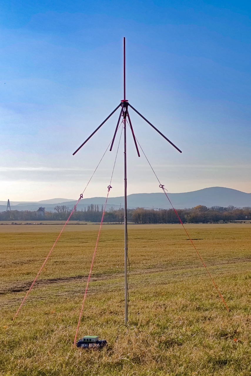
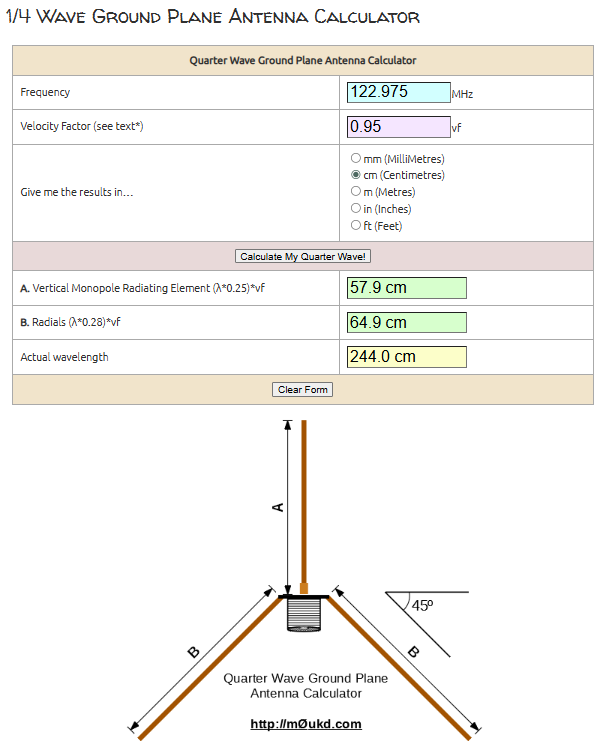
After some consideration, I decided to go with the good old 1/4 Wave Ground Plane Antenna. On M0UKD’s amateur radio blog, there’s a simple yet effective calculator that can be used to determine the antenna dimensions.
The frequencies used by aircraft range from 108 to 137 MHz, with the center of the band around 122.5 MHz. Near us is Budapest Liszt Ferenc International Airport (LHBP), where the approach control frequency is 122.975 MHz—practically in the middle of the band. For this reason, I tuned the antenna to that frequency.
This is a true unbalanced antenna with a feed impedance of around 50 Ω, making it an excellent match for 50 Ω coaxial cable, it can be connected directly, with no need for impedance matching.
Such an antenna is easy to build, and you can find several good examples on M0UKD’s calculator page. He typically uses aluminum or copper tubing, but he also has an interesting model that works on any frequency between 80 MHz and 410 MHz, and both the monopole and the radials are made from extendable telescopic antenna rods. This is a great idea, but if left outside in the yard for a long time, the rods will eventually rust.
Another issue with aluminum and copper tubes is that they have become quite expensive lately: a 1-meter piece costs about €2.5–€5. Since this antenna needs a quarter-wave (λ/4) vertical monopole and at least four radials that are about 12% longer, you would need at least five 1-meter tubes or two 2-meter rods—costing roughly €10–€20 in any case. Moreover, thin metal tubes dent when bent, which means that if the antenna gets damaged, the affected element is basically scrap.
What I wanted was an antenna that can be transported (collapsible if necessary), can also be permanently mounted on the balcony, withstand the elements, and—on top of that—be extremely cheap. I wanted something I could put up and forget about…
The solution turned out to be plastic (PVC) electrical conduit, which is available in 2.5 m lengths for about €0.75–€1 each. Of course, the PVC tube itself is non-conductive, so to use it as an antenna element, a stranded copper electrical wire needs to be pulled through it. The five tubes connect at the center to a hub, which holds the BNC connector for attaching the coaxial cable, allows the antenna to be mounted, and lets the radials fold in or swing out into the proper 45-degree position.
3D printing and assembly
The STL files for 3D printing can be downloaded from Printables.com.
The rods (monopole and radials) are made from ∅14.6 / 13.5 mm PVC electrical conduit. The pieces must be cut to the required lengths as calculated by the dimensioning program. The antenna can of course be built for other frequencies as well, using different dimensions.
3D printing is used to produce the central “hub”, the end plugs for the rods, the hinges of the radials, and the spacer that holds the radials in the folded position (shown in red in the photo).

For outdoor use, PETG is a particularly suitable filament choice for these parts. Unlike standard PLA, PETG tolerates prolonged exposure to sunlight much better: it does not become brittle as quickly under UV radiation and maintains its mechanical strength over time. It is also far more resistant to moisture, temperature cycling, and general weathering, which is critical for an antenna that may be deployed outdoors for extended periods. PETG remains dimensionally stable in summer heat where PLA would soften or deform, yet it is still easy to print and does not require the high temperatures or enclosure typically needed for ABS. This combination makes PETG an excellent compromise between durability, printability, and long-term reliability in outdoor antenna applications.
A stranded 1.5 mm² electrical wire is inserted into the monopole and the radials. The wire ends are fixed inside the plugs (glued in place before inserting the plug).
A BNC connector is mounted inside the hub; the monopole is connected to its center pin. The radial wires are soldered to a washer‑shaped plate. I cut this washer from a piece of PCB material, but other solutions are also possible—for example, a galvanized lid from a tin can works just as well. Four M3 brass inserts are also installed in the upper part of the hub so that the two printed parts can be screwed together.

The antenna mast was made from one section of an old, discarded hiking tent pole: a lightweight, collapsible aluminum tube. The “Connector” part was designed specifically for this mast. For a different mast, this part will most likely need to be modified. Using the four screws, the hub can in practice be mounted to almost anything, including a more robust mounting plate.
Up to the mountains!
When folded for transport, the whole antenna is only about 75 cm long, and—with the mast included—weighs roughly 550 g. Strapped to the outside of a backpack, it’s easy to carry on a hike. On a sunny day you can set it up on a hilltop and listen to the airband traffic of airports within roughly 70–100 km.
For VHF, reception is largely limited by (quasi-)optical line of sight: what is below the radio horizon will usually not be heard. A useful approximation for the radio horizon is:
(with d in km and heights in meters). Aircraft are high above the ground, so you can often hear them from much farther away than the airport itself. A typical airliner cruising around 10,000 m (≈ FL328) can be received from about 350–450 km under normal conditions. Humid or foggy weather may reduce the range slightly, while rare “super‑propagation” (temperature inversion/ducting) can extend it beyond 600 km.
Have a great trip!